Low light focus accuracy with the Pentax K-5 camera
– White Paper –
LumoLabs (fl)
(Falk Lumo, f a l k @ f a l k l u m o . c o m )
|
Version: |
1.3 of Mar 26, 2011 |
|
History: |
1.3: Chapter added about improvements made in firmware 1.03 |
|
Status: |
Final |
|
Print version: |
|
|
Publication URL: |
|
|
Public comments |
blog.falklumo.com/2011/02/lumolabs-pentax-k-5-low-light-focus.html |
This paper studies the performance of the Pentax K-5 digital SLR camera phase detect autofocus system in the presence of low and very low luminance levels. The study was inspired by the vast number of complaints that the camera systematically misses focus in low light, particularly low tungsten light. The author has reasons to believe that his findings apply to almost all shipping K-5 cameras until the present date. The results therefore can be used to estimate the region of light values where the K-5's AF system works as advertized. And where it doesn't. Cameras from other vendors may show a similar behavior (I've seen corresponding reports).
All content in this paper is © 2011 author.
A first reading of LumoLabs' white paper
-
●."Understanding Image Sharpness" [www.falklumo.com/lumolabs/articles/sharpness/]
is highly recommended and assumed throughout the current text. It is cited as "UIS paper".
1. Summary
In modern times, each new release of a digital SLR camera seems to be accompanied by teething troubles. This applies to all makes across the board. Sometimes, they are fixed quickly by the vendor, like the "Green Line Syndrome" video issue in the Pentax K-7, the "Hot Pixel" video issue in the Nikon D7000 or the "String of Pearls" stain issue in the K-5. Sometimes, they aren't like the shutter-induced blur issue with the K-7 which LumoLabs succeeded to document.
Currently, the most significant remaining teething trouble for the K-5 which is widely reported is a systematic wrong lock of autofocus in low (tungsten) light.
Pentax has officially released a fix for the issue, deployed by the firmware release 1.03. So, the current version of this study (v1.3) looks at the situation before and after the fix has been provided. Most of the text applies to the situation prior to the fix. The changes brought by the firmware 1.03 fix are studied in a separate chapter.
I shall first look at the actual performance (accuracy, not speed) of the K-5 phase detect autofocus (AF) module. Then, I'll try to clarify the inner workings of the AF module a bit in an attempt to evaluate if the performance can be improved in firmware.
2. Testing methodology
All tests are performed with a single K-5 camera. No second sample was evaluated. However, a Spanish Pentax dealer (Pentaxeros) has tested 100 consecutive cameras and found no significant differences in AF performance. Moreover, an experienced service technician from Pentax has unofficially confirmed that the low light performance issues apply to all units and can't be fixed by a unit exchange. Therefore, the test with a single sample may be good enough in this case.
The tested Pentax K-5 sample is made 2010, October 11 using firmware version 1.01.00.05. It was the current release when I started testing but it isn't the newest version now. However, newer versions did not improve on the issue (reportedly) and haven't been advertized to provide a fix either.
2.1. Testing situation
The K-5 is mounted on a tripod with the optical axis perpendicular to a wall with a test chart attached to it in the middle. The test chart is as depicted in Fig. 4 in the UIS paper, tilted 5° such that the level guides become horizontally aligned. It is important to verify the perpendicular alignment to the wall. I use a 90° angle bracket and control that one bracket disappears in live view, holding it horizontally and vertically. Smarter methods exist, including a box with a hole and a mark. The actual exposures are taken with 3 s mirror lockup and a remote trigger.
The bulk of tests was done with an FA 31 mm f/1.8 Limited lens (silver finish :) ) and 1 meter distance (which is approx. 32 times the focal length). Other tests include a DA* 60-250mm f/4 at only 3 meters distance. The (only) light source is located at a 30° angle from the test chart at about 1 meter distance as well. The following drawing (Fig. 1) illustrates the testing situation.
The important detail here is the light source: I used 3 tungsten bulbs of 40 W each where each bulb was controlled by an independent dimmer varying the bulb luminance between 0% and 100%.
40 W is pretty weak and even 3 of them don't provide much light. Therefore, I had to place them rather close to the chart (about a bit more than a meter) using direct illumination.
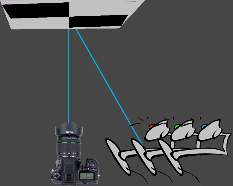
Fig. 1Testing situation for focus test. The camera looks perpendicularly at a test chart illuminated by a light source at an angle of approx. 30°. The chart's black quadrants are tilted 5° against a horizontal level.
The light source is made of 3 lamps with a 40 W tungsten bulb each, in one of the colors red, green or blue, and each one controlled by a dimmer. There are no other light sources, the camera is shaded from the light and the illumination color and brightness across the test target is about constant.
The distance between camera and chart was kept close to 32x the focal length.
2.2. Determination of light source luminance and color
Because the target mainly is a white wall, I used Tv auto-exposure and +2 EV exposure compensation. This gave me well lit raw images as to be expected from a camera calibrated to expose a uniform surface (like a white wall) to 18% gray. White balance was set in-camera to daylight which is 5550 Kelvin. I then imported all RAW images into Lightroom 3 using zero brightness, contrast and black level (which differs from the Lightroom default setting).
No image was clipped. However, images with a high percentage of red would clip the red channel upon export to sRGB JPG. I therefore corrected all exposures by -1 EV prior to export to sRGB JPG. I then compute and add two light values (in EV):
-
1.LV1: The exposure EV (as determined by EXIF: ISO, shutter speed and aperture) +1
(addition of 1 corrects for the -1 EV correction in post processing not reflected in the EXIF) -
2.LV2: log2(Y) [EV] where Y is the brightness of the white image area near the center.
I use brightnessY = 0.299 R+0.587 G+0.114 B (1)
which is a common conversion formula, and (R,G,B) = (Rs/255,Gs/255,Bs/255)2.4 are computed from the pixel values after conversion to sRGB using the Lightroom export function. The exact sRGB conversion function is a bit more complicated but you get the idea...
-
3.LV = LV1 + LV2
Note: LV2 is always negative, LV < LV1!
The resulting luminance levels are pretty low and may be lower than what is reported by other testers or using an external light meter. This is why:
-
●.An automatic exposure would yield values higher by about 2.4 EV (due to the 18 % gray calibration). Most testers do not correct for this.
-
●.In tungsten light, the red component dominates. If only red is recorded, a fully saturated exposure would have a brightness Y of only 30% or -1.7 EV. I calibrate for Y, most testers calibrate for max. channel saturation (or not at all).
-
●.Both effects combined can lead to EV values which are up to -4 EV below the values other testers would report for the same testing situation. Please take this into account!
However, in order to have a level playing field to judge the camera performance, I compute luminance as defined above and which about replicates the condition for the AF module. Moreover, the Pentax-specified AF working range (≥ -1 EV) may be meant in the same way as defined here.
Color is defined by the linear RGB color of the white image area near the center, normalizing all three channels by a factor such that the maximum channel equals 100%, using the daylight white balance input image. I originally wanted to compute color temperature and tint but the light source colors turned out too extreme for that.
The measurements using the above testing situation spawn a range of about -3 EV to +2 EV which is where the K-5 phase AF locked focus. By itself, this is a pretty impressive performance exceeding my expectation! At the darkest levels, the AF requires a manual prefocus to lock. It locks where I can't see anymore and I sometimes used a flashlight for manual prefocus ;)
The colors spawn a range from deep red (far below 2000 K) to blueish cold (12,000 K). The red tungsten bulb emits red only. The green tungsten bulb emits about equal amounts of red and green. And the blue tungsten bulb emits like the green one plus about half the amount of blue. So, the red bulb is fire red :) , the green is yellow rather than green (still looks green to the human eye though ;) ) and the blue is cold daylight rather than blue. In retrospect, a cold LED light source with color filters would have spawned a larger color space. However, I think we covered a large enough portion of the color space for our purpose.
Below are four original color patches (1:1 crops) after sRGB export:


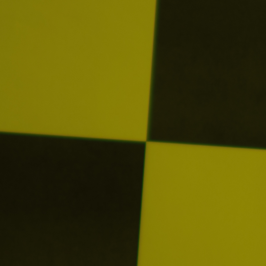

Fig. 2 Four center crops (100%) from the test chart shots.
The 100% crops are best accessed by opening the images in a new window using this paper's web version.
The difference between the first and second sample in the upper row is 0.7 EV (right is lower light).
2.3. Determination of focus accuracy (defocus magnitude)
I use a physical measure of focus accuracy: the difference (length of the distance along the optical axis) between the sensor plane and the image focus plane. I call this value "defocus df" and it is measured in µm. Of course, an ideal AF module would match both planes and df=0. A real AF module introduces blur due to a finite df. Note that even with exact focus, an image will have blur due to other factors.
The focus accuracy is computed numerically. The method is described in chapter 2.1 of the UIS paper (version 1.1 or later). I use the "soft setting" but I applied 0.5 px / 100% sharpening in Lightroom 3. Using the slanted edge method (I used QuickMTF and γ=0.45) I determine the edge blur b in pixels (10% - 90% rise width). Again, refer to the UIS paper for details.
The overall edge blur in pixels is larger than the fraction due to defocus. So, I first determine the amount of blur bdefocus which is due to defocus alone:
where I used b0 from best focus measurements to be approx. 2.19 px. This value is in line with our so-called "soft setting" plus sharpening applied for a lens at its max. f/1.8 aperture. There is a chance however that I underestimate static blur b0 for f/1.8 and daylight. Because chromatic aberration could increase static blur beyond the best values which are measured in (monochromatic) red light. The effect however is small enough to be ignored within the scope of this paper.
Eventually, I relate defocus edge blur bdefocus and the circle of confusion diameter and obtain for the defocus distance df:
df = (7.00 µm) bdefocus[px] N (3)
where N is the lens aperture's f-stop number. The factor 7.00 µm is derived from the size of a K-5 pixel and the theoretical relationship between edge blur width and the circle of confusion as published in the UIS paper (version 1.1+).
2.4. Determination of focus direction (defocus sign)
The above testing method provides the magnitude of defocus but does not immediately provide the direction of it (its sign). So, here comes a separate method of determination of the sign. First, let's consider an in-focus image of a tilted test chart (cf. Fig. 3).
The edges show color seams as emphasized in the following table:
 |
 |
|
Backfocus = magenta color seam |
Frontfocus = green color seam |
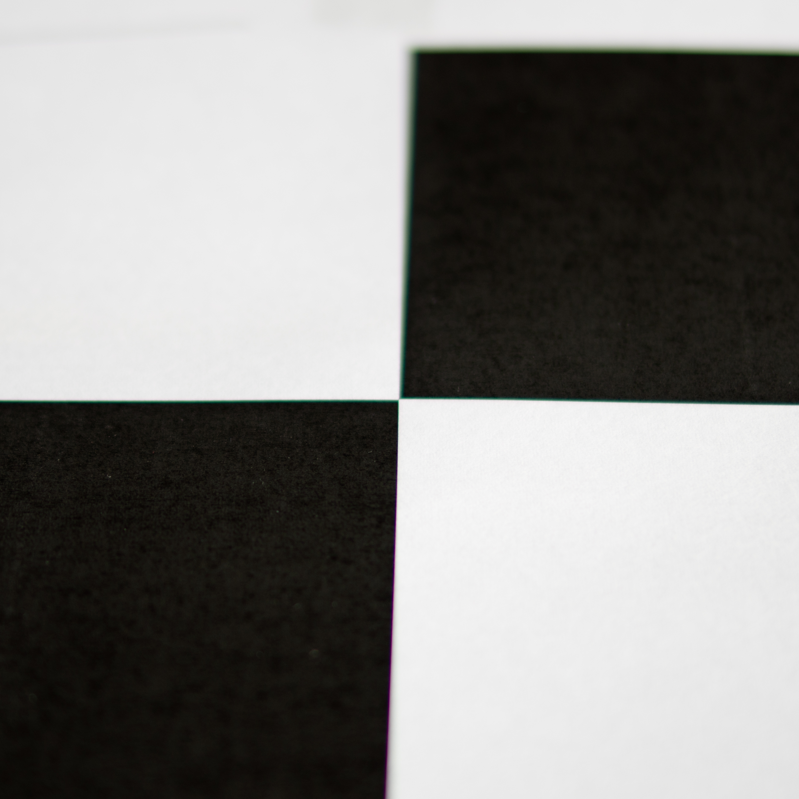
Fig. 3: An image of a tilted plane (normal perspective, i.e., the bottom half is more nearby).
The bottom half shows an edge if the camera focusses behind it (back focus) while the upper half shows an edge if the camera focusses in front of it (front focus). The table shows edge enlargements with the back focus edge turned 180°. The images are taken with the Pentax FA 31 Ltd. lens at f/1.8.
Note that the center is slightly defocussed. The AF was pointed at (almost) exact center. This is typical for AF sensors spanning a finite region, i.e., it can focus on any feature within its sensitivity region.
So, we can determine the sign of defocus by the edge seam color:
-
●.green = front focus = + sign (actual image distance is too large), i.e. df > 0.
-
●.magenta = back focus, i.e. df < 0.
Magenta is the complementary color of green (blue+red) and the colors are the primary correction colors of an achromatic lens doublet which brings blue and red to a common magenta focus (different from green). An apochromatic lens (e.g. a lens with no CA (color aberration) at all) will bring all three colors to a common focus. But due to the finite dispersion of glass, the achromatic rays (magenta and green) would still differ out of focus leading to the seams called Bokeh-CA or Bokeh-Fringing. Note that Bokeh-CA is not a lens aberration and rather universal. Therefore, we may assume that our rule can be applied rather universally too (applicable to lenses with a positive rear lens element and normal dispersion).
In practical terms, the green fringe is sometimes surrounded by a fine magenta seam on the bright side of the edge. If in doubt, the color on the dark side of the edge matters, i.e., the color with the larger seam width.
3. General remarks regarding normal focus accuracy
What I found over a large range of lenses, apertures and situations (excluding difficult situations) is that defocus varies over a range from about 30 µm to 100 µm with 70 µm being a good a priori estimate.
This helps us to get a feeling what magnitude of focus variations we may still consider normal.
Note: A narrow region around 0 µm is typically absent from most measurements as we derive defocus from squared blur values (cf. eq. 2) and the error in the static offset b0 causes a single-sided error margin. If you like, feel free to subtract up to ≈ 20 µm from some defocus measurements. The problem is you don't know which ones. In other words, recalibrating the lens would not populate an empty region around zero. An independent determination of b0 for every measurement point would.
Contrast AF for the K-5 is a bit more precise with defocus varying from 10 µm to 50 µm with 30 µm being a typical value. I.e., K-5's contrast AF is about twice as accurate as phase AF.
Canon once specified that their phase AF has an accuracy of at least a=1/3× the circle of confusion for "all" lenses when using their best cameras (and of at least a=1× the circle of confusion for non professional cameras) [many citations found but no root source; e.g. PDF at dougkerr.net/pumpkin/index.htm#AutofocusAccuracy]. That's a technically flawed specification. So, I translate this to mean 1/3 the circle of confusion for f/2.8 lenses using an f/2.8 AF center sensor (or for f/5.6 lenses using an f/5.6 AF center sensor for cameras not sporting a wide center sensor). Using a circle of confusion of 20 µm for APS-C, N=f/5.6 and a=1, this translates to df ≤ 112 µm which is almost exactly the same as our finding for the Pentax K-5. In other words, focus tolerances df of up to 100 µm are normal (for non professional cameras) even if this is probably shocking news for pixel peepers ;) Of course, an f/2.8 wide AF sensor in a professional full frame camera (coc=30 µm, a=1/3) would bring this down to 30 µm. It is a pitty that Pentax didn't include at least an f/2.8 wide center AF sensor as it is needed really to exploit the K-5's high resolution. With its current phase AF accuracy, f-stop figures around f/8 to f/11 are required to bring bdefocus down to about 1 px (f/4 with contrast AF).
BTW, this is why LumoLabs asks for, e.g., a [-60, -30, 0, 30, 60 µm] 0.7 s focus bracket function (depends on the selected f-stop) with automatic preservation of the sharpest (highest contrast) in any APS-C camera. It's fast to auto-select the sharpest from a buffered set, e.g., I know the algorithm.
The data backing the statements in this section are presented below (cf. Fig. 10 and 11 on p. 17ff).
4. Low light focus test results (firmware 1.02)
I made about 300 measurements, varying luminosity, light color, aperture, focal length, lens, distance and focus method. I took me ages to find a good way to present the data in a meaningful way, both for me to understand what's going on and for presentation. The final outcome turned out to be a simple solution. However, it already includes the choice for luminosity normalization for various light colors (eq. 1) and the defocus normalization for various apertures (eq. 3). I.e., both are the result of quite some experimentation to factor out the most significant variables.
4.1. AF assist light
The Pentax K-5 sports a (green) AF assist light which comes on if the scene is too dark. As it turns out, it had no measurable impact on test results and most results shown are for AF assist light switched off.
First, AF assist light engages too late. i.e., it stays off in situations where the K-5 doesn't focus correctly.
Second, even if it engages, it engages only for the initial (prefocus) measurement. All subsequent (hunting) adjustment steps are carried out without AF assist light (in the dark) with the result that the same focus as with no assist light at all is locked. This is a clear indication for at least one firmware bug (explained by the fact that the AF module requires more light if out of focus itself because the two phase signals are more blurry (have less contrast) then as well). I.e., the AF module measures and decides that it has enough light to focus properly (when the pattern turns sharp).
Two possiblities:
-
1.The AF module is right and it has enough light. I.e., the problem is elsewhere. Or
-
2.The AF module is wrong and it doesn't have enough light. But it thinks otherwise.
Both would be a bug in the firmware which is (#1) or adds to (#2) the problem.
Interestingly, this seems to be the normal case and is reported for both 1.01 and 1.02 firmware releases. A minority reports AF assist light works as expected (engages several times) and then achieves correct focus. These reports confirm that at least theoretically, the AF assist light can engage repeatedly during an AF operation and that if it doesn't, it decided to do so.
Further tests have revealed that the AF assist light behaviour actually depends on the light level: At high enough light levels, it stays off. At low enough light levels, it stays on for the entire focus operation until final confirmation resulting in correct focus. At some intermediate level, it only comes on for the first measurement but stays off for the fine calibration steps resulting in a false focus.
Therefore, it can be concluded that the AF module takes an autonomous decision wether it requires the assist light, based on luminosity and contrast only and ignoring the potential trouble of a colorimetric sensor.
4.2. Constant lens, aperture and distance
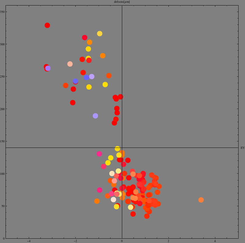
Fig. 4Focus accuracy of the Pentax K-5 camera in low light, using the FA 31 Limited lens at f/1.8 in 1 meter distance.
Each dot represents one measurement. The horizontal axis corresponds to the luminosity (the light value in EV) which the focus operation was performed at (ranging from -5 to +5).
The vertical axis corresponds to the focus accuracy (defocus df) in µm (ranging from 0 to 360 µm). In this case, you may divide µm by 12.6 to obtain the defocus blur width in pixels. I.e., the 140 µm line corresponds to 11.1 pixels. To be precise, 11.1 px on top of the static blur of 2.2 px which adds up to 11.3 px (Kodak formula with p=2).
The color of each dot represents the daylight normalized sRGB representation of the light color which the focus operation was performed at. I.e., each dot color has one saturated channel in the chart to make them equal brightness (brightness is encoded in the horizontal position, not the dot brightness).
Caption continued on the next page...
The vertical line is at 0 EV and Pentax specifies an operating range of EV ≥ -1.
The horizontal line is at 140 µm and marks the transition to bad focus. Typical normal focus is at ≈ 70 µm or the middle of the bottom section.
Note: cf. text for a correct interpretation of EV levels (or add 2±2 EV)!
Note: Every dot in the upper right quadrant (or the upper left quadrant near the lines) fails to meet Pentax' advertized specification.
BTW, this chart is nothing less but four-dimensional. Enjoy :)
First, in Fig. 4, I present a subset of results, all made with the FA 31 Ltd. lens at aperture f/1.8.
Therefore, lens, aperture and distance within this subset of results is kept constant. Before we discuss the significance of these other 3 variables, let's discuss the current result, i.e., the significance of varying light color and light luminosity.
Finding 1: The focus accuracy makes a sharp transition
from df ≤ 100 µm (ok) to df = 250±70 µm (fail) at ≤0.5 EV.
Finding 2: The first very inaccurate focus results (>200 µm) emerge at 0.0 EV for very red light.
Finding 3: For colder light, the transition is moved to dark:
For tungsten/orange light, it emerges at -0.5 EV;
for daylight/blueish light, it emerges at -1.0 EV.
Finding 4 (Corollary): For EV as derived from exposure reciprocation (i.e., only using the light meter's readings for shutter, aperture and ISO), first inaccurate results appear at +4 EV (cf. discussion in section 2.2. ) while the camera may focus ok at -1 EV under optimum conditions (daylight, bright contrast-rich feature on a darker subject). Therefore, anecdotical testing reports should be expected to yield contradictory conclusions.
Finding 5 (Corollary): A color brightness conversion formula like eq. 1 on p. 3, but using a factor smaller than 0.299 for red, could have yielded a transition behaviour which is almost color independent (weighted luminosity only).
In other words, one plausible hypothesis is that the lack of focus accuracy is due to a lack of light reception accompanied by a relative (although not total) color blindness for red of the AF sensor.
Note: We will refer to the defocus magnitude of df =250±70 µm as ≈ 250 µm. Do not mistake this for a constant defocus. It still varies within a 50% larger range than a normal focus would, i.e., within a range of 140 µm. Of course, the extra 50% could be due to low light.
4.3. Direction of defocus
Let's take a look at defocussed sample images to determine the direction of defocus.
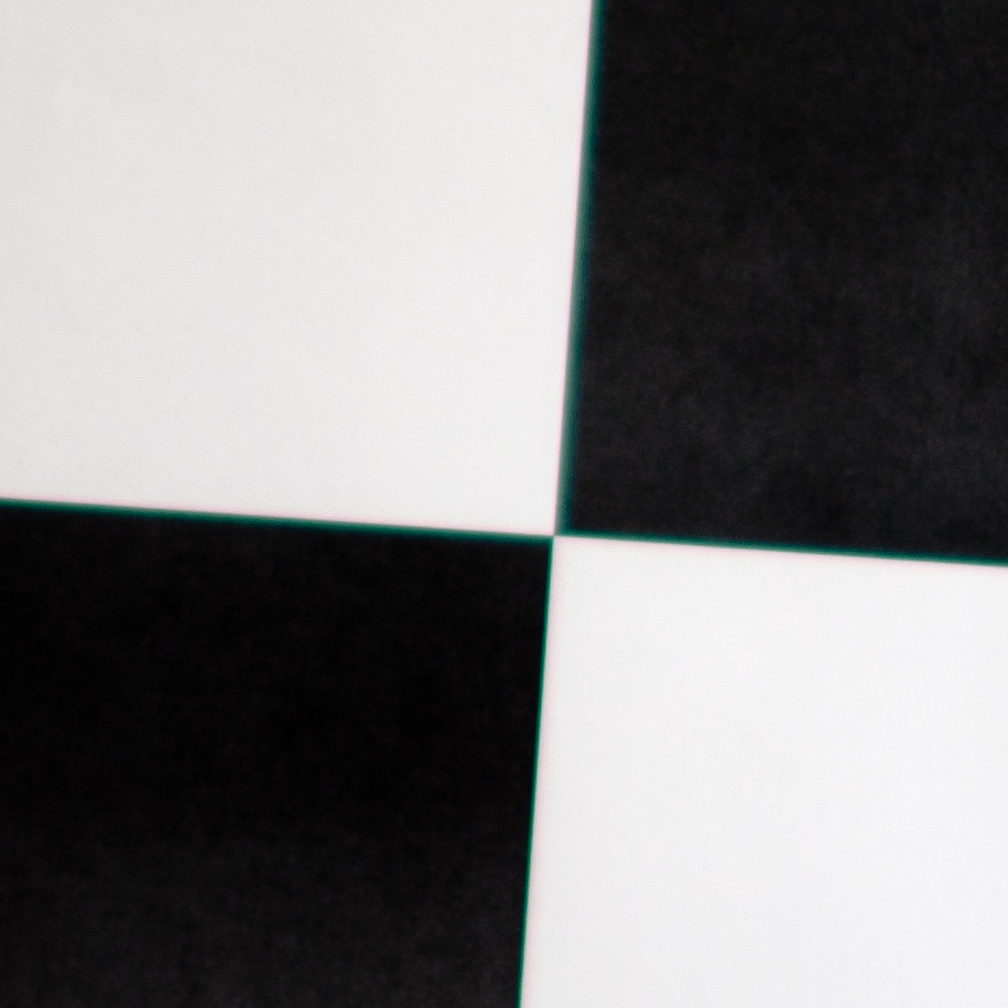
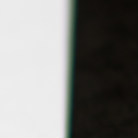
Fig. 5: Typical edge seam color for large values of defocus df. Image shown is after white balance correction.
It wasn't possible to determine the direction of defocus for all images. That's because some of the light colors have been too extreme to allow for seam colors at all. E.g., there is no seam color in monochromatic red light. However, in all cases where the seam color was visible and the defocus was significant, it was green.
Finding 6: df > 0; i.e., the direction of defocus is deterministic.
In the regime of inaccurate focus, the camera does always front focus.
Finding 7 (Corollary): It would be possible to correct for the defocus, e.g., by an operation
df ← df - 250 µm (the result wouldn't be satisfactory but better).
At 1 m distance, the magnification of an 31 mm lens is M=32 (1000/31; actually, it is 31 after taking the final distance into account). Therefore, M2 ≈ 1000. This means (cf. UIS paper, formula for shift s) that the amount of front-focus in subject space is about 250 mm or ¼ the subject distance (focus is at 75 cm rather than 100 cm).
4.4. Dependency on aperture
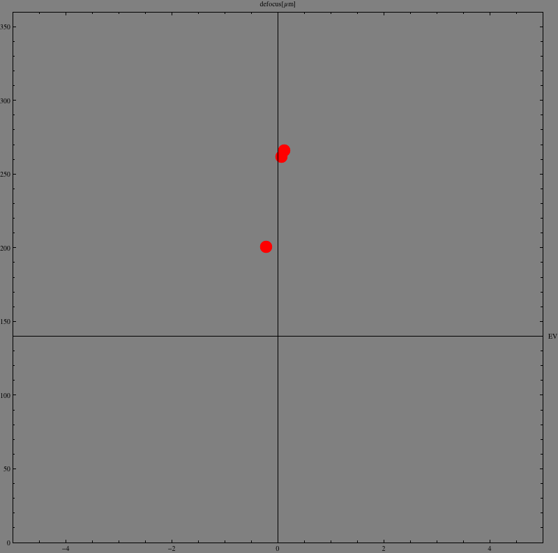
Fig. 6: Results for FA 31 Ltd. at f/1.8 (lower dot), f/2.8 and f/4.0. Add all previous dots for f/1.8 too.
(Cf. caption of Fig. 4 on p. 10 for an explanation how to read the chart and interpret the EV scale.)
I found no strong dependency on aperture, studying the FA 31 results (shown above) or for other lenses (not shown yet). Of course, the blur is less at smaller apertures. But that's already covered by eq. 3 on p. 6.
Finding 8: The defocus (offset of the focal and sensor planes) is independent from the lens' aperture.
4.5. Dependency on focal length
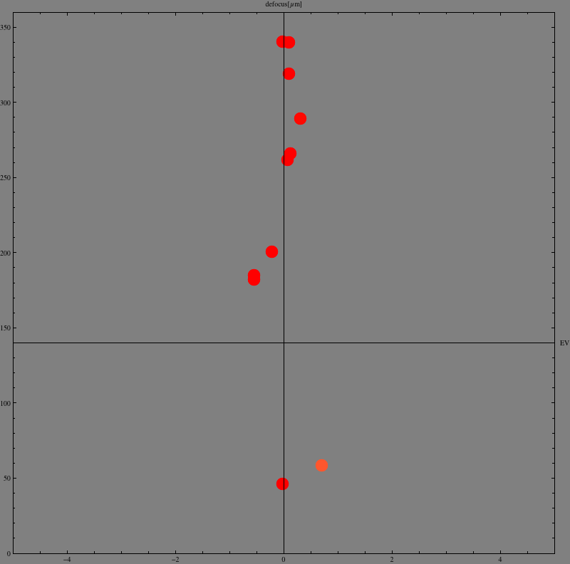
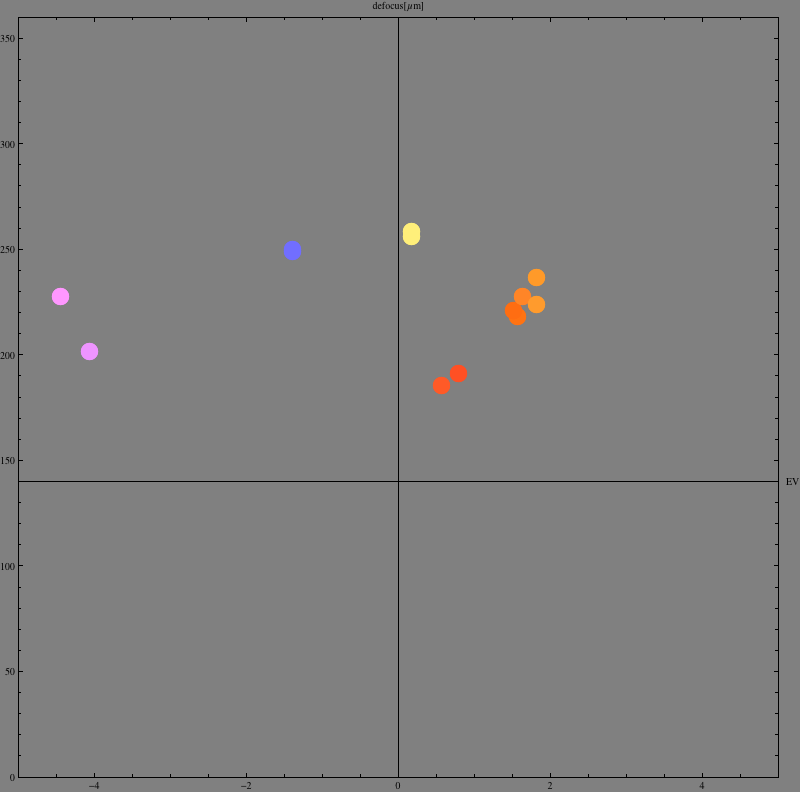
Fig. 7: Left image: Results for DA*16-50 at f=16 mm, f=31 mm and f=50 mm. The threshold seems to be the same. The large variation around EV 0 is erratic. e.g., the lowest and largest value are both at 31 mm f/2.8. The "good" dot at 0.7 EV is at 50 mm f/2.8. The three dots for the FA 31 from the previous figure are kept in this figure.
Right image: Results for DA* 60-250 at f=60 mm and f/4 to f/4.5 at 1 m. The right image serves as a reference for comparison with Fig. 8 and should not be compared directly with the DA* 16-50.
(Cf. caption of Fig. 4 on p. 10 for an explanation how to read the chart and interpret the EV scale.)
I found no strong dependency on focal length. The DA*16-50 results don't cover an interesting enough region to confirm this. But the (non existing) differences between 60 mm and 200 mm for the DA*60-250 lens (shown below) are another indication. The direct differences between the 50 mm and 60 mm values (esp. at 0.7 EV) are not due to the focal length as to be shown below.
Note that the AF for the DA*60-250 lens reports focus lock at -4.5 EV ;) (to be fair, it only does so after manual prefocus – but nevertheless, this is dark!)
4.6. Dependency on distance
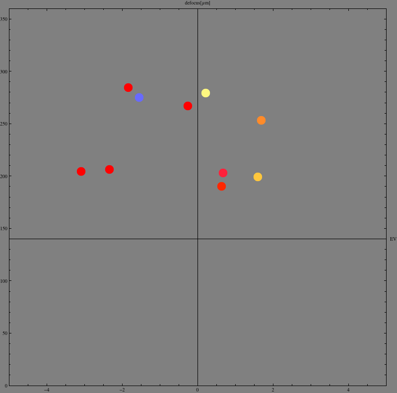
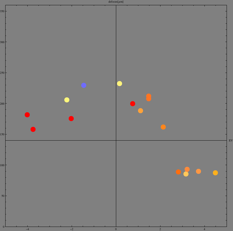
Fig. 8: Left image: Results for DA* 60-250 at f=200 mm and f/4 at 1 m. To be compared with the right image in Fig. 7 which shows the same but at f=60 mm.
Right image: Results for DA* 60-250 at f=200 mm and f/4 at 3 m distance.
(Cf. caption of Fig. 4 on p. 10 for an explanation how to read the chart and interpret the EV scale.)
The results for the distance of 3 m show no significant difference with the results at 1 m except that they cover a larger parameter space. Theoretically, the results at 1 m could be "worse" than at 3 m but I don't believe so. I just missed a bright enough test shot for that lens at 1 m...
Finding 9: The defocus is independent from the lens' focal length and from the subject distance.
Finding 10 (Corollary): The defocus is independent from the magnification M
(at least for moderate values below 1:10).
4.7. Dependency on the lens
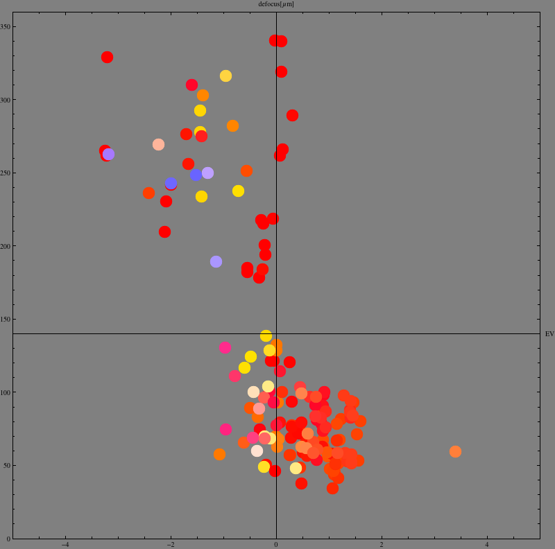
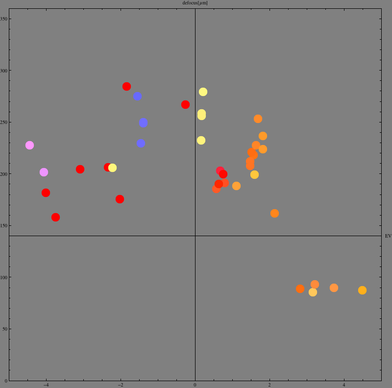
Fig. 9: Left image: All results for the FA 31/1.8 Ltd. and DA* 16-50/2.8 lenses, ranging from 16 – 50 mm.
Right image: All results for the DA* 60-250/4 lens, ranging from 60 – 200 mm and 1 – 3 m distance.
(Cf. caption of Fig. 4 on p. 10 for an explanation how to read the chart and interpret the EV scale.)
Surprisingly, the EV value of transition is shifted to significantly larger values around +2 – 2.5 EV.
Finding 11: The defocus is dependent on the lens and the transition point can shift up by at least 2 EV. We have no data about the nature of the dependency. It could be related to differences in nominal lens apertures, i.e., its maximum f- or t-stop.
Hypothesis: The transition point's EV value is a constant plus + 2 log2 (max. f-stop N).
So, the lens does play a significant rôle. In worst case circumstances, a 250 µm front focus could emerge at +6 EV perceived illumination.
I don't know what is the decisive factor. One possible effect could be the total amount of light entering a lens. 2 stops roughly is the difference between f/4 and f/1.8. Theoretically, a phase AF module cannot use the extra light entering the outer parts of a lens aperture and is limited to its measurement base aperture which is a bit less than f/5.6 for the K-5. But the component which makes the AF module fail and lock false focus may be susceptible to the total amount of light. Theoretically, it could be the assumed AF module's color temperature sensor. There is no reason this sensor should be confined to receive only the masked out parts of the light entering the AF module.
On the other hand, the difference between the f/1.8 FA 31 and f/2.8 DA*16-50 lenses was less significant. But it's not excluding a 1.2 stop difference in the transition EV value either.
Note: Finding 11 isn't easily obtained by a study which just looks at blur. Because a lens with a smaller nominal aperture cannot be opened as much and therefore, has less blur to start with. It then requires an exact measurement of blur and cannot be done by simple visual inspection anymore.
Pentax may be well advised to repeat my work for lenses with a nominal aperture of f/5.6. Or to make a lens cap mask with a ∅ ≥ f ÷ 5.6 hole blocking the light entering the outer parts of a faster lens; in order to see if the transition point shifts with the mask hole diameter ∅.
4.8. Overall results
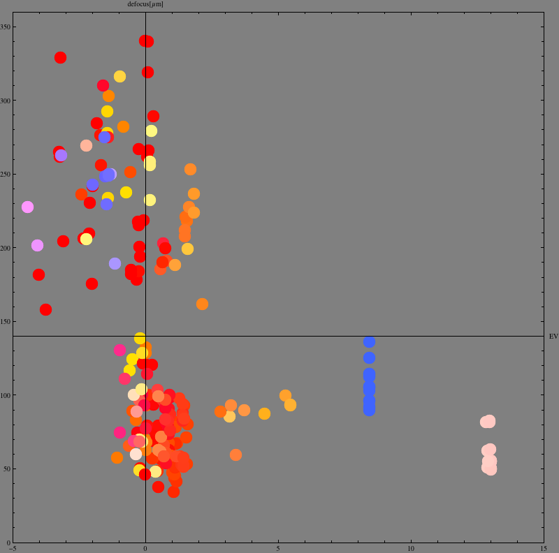
Fig. 10: Defocus for phase AF, all results.
Unlike previous charts, this chart spans EV -5 to EV +15. All results are shown, i.e. for all lenses.
The results at EV 8.5 and EV 13 are obtained with the FA 31 at f/1.8 and at 1 m distance in daylight (shadow and direct sunlight, resp.).
(Cf. caption of Fig. 4 on p. 10 for an explanation how to read the chart and interpret the EV scale.)
The accuracy in the (blueish) shadow at EV 8.5 is a bit disappointing. While within specification, one could have hoped for better accuracy. I checked for the direction of defocus and all appear to be a bit front focussed.
Probably, a focus calibration for this lens could improve the results. On the other hand, the results for plain sunshine and tungsten show that the adjustment range is limited anyway (maybe 20 µm).
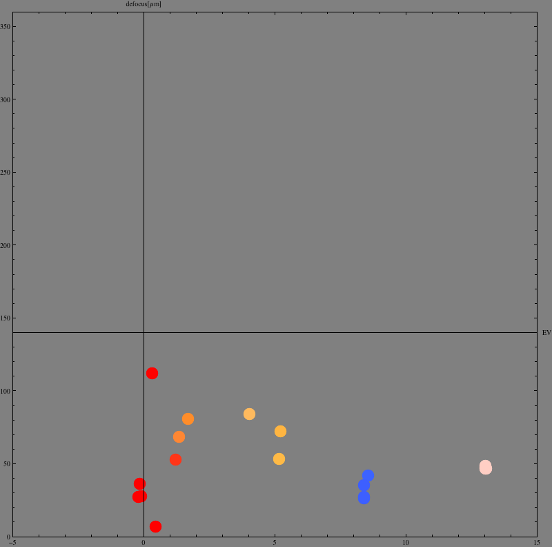
Fig. 11: Defocus for contrast AF, all results.
The direction of defocus varies between front focus and back focus. Some results around EV 0 have been obtained by manually guiding the contrast AF system though.
(Cf. caption of Fig. 4 on p. 10 for an explanation how to read the chart and interpret the EV scale.)
While the accuracy of contrast AF is pretty good (as has been reported already) and beats phase AF accuracy by about a factor 2, it has its own weaknesses nevertheless.
First, in low light it would lock in arbitrarily false positions. As it is easily spotted, I excluded all such results by simply not taking a photo. Sometimes, it would walk thru the good position only to jump to a false lock then. Some results in the chart above are obtained by help of a flash light and refocus starting from an in-focus position. The AF routines are certainly not yet what they could be.
Second, contrast AF accuracy can be made about 10 µm by clever coding and using subpixel information (better with a sensor allowing windowed readouts). There is significant room for improvement as well and contrast AF could make use of a speed/accuracy priority option (btw., all results are obtained with AF.S and accuracy priority). E.g., contrast AF must avoid to reverse operation during the focus fine adjustment phase (and it can be done).
I allow myself above two statements because I once coded a contrast AF algorithm myself (in an industrial context).
I heard that firmware version 1.02 has slightly better contrast AF code. I didn't test it out.
4.9. The Red target
With version 1.2 of this paper, I introduce another test: the Red target test.
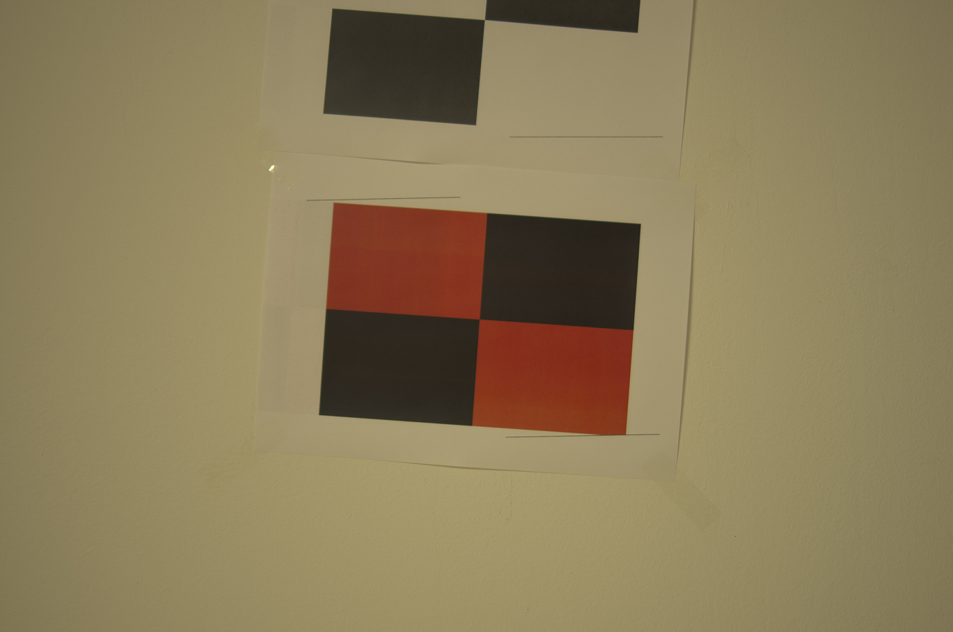
Fig. 12: A variation of the slanted edge target using red rather than white quadrants (the center chart). This makes no different AF target with tungsten light (left) or red light (right) and measurements for both situations would be registered by similar (red) light color dots in the AF charts as displayed here in the paper (both images are displayed using daylight color calibration).
However, in the presence of tungsten light, other metering spots (like other AF points or other 77 zone metering points) don't see the center AF spot's color. While in the presence of red light, they do.
The Red target test should be able to clarify if other than the center metering spot contribute to a correct AF metering when light is low (hoping that tungsten and red aren't treated equal internally).
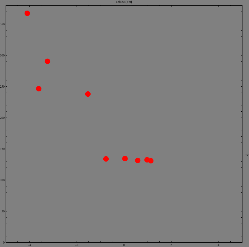
Fig. 13: The Red target AF performance with tungsten light (left) and red light (right).
The results aren't very significant. But there is a miniscule hint that the firmware may be using alternate metering information at low light levels in an atempt to improve color metering accuray in a region unaffected by the focus shift. But that this doesn't help prevent the focus shift.
The results are from the FA 31 Ltd. at f/1.8 at 1 m distance and white balance set to Daylight.
The Red target test suggests that the K-5 firmware (version 1.02) may use additional colorimetric information from outside the AF point to improve focus accuracy but that it doesn't lead to avoiding the focus shift, at least not with a lens as fast as f/1.8.
Finding 12: The focus shift is independent from color variation outside the focus spot.
4.10. Hypothesis promoted to Theory
After version 1.0 of this paper was published, a number of tests was drafted and carried out in order to test the hypothesis after Finding 11 on p. 16. All results are published here:
The results can be condensed into the following theory:
Finding 13 (Theory): The (color-weighted) luminosity of the transition (below which the focus shift appears) is exactly proportional to the overall luminosity falling onto the focus screen (ground glass).
Finding 13 (Corrolary): The transition is shifted to brighter luminosities (is worsened) if:
- The lens is slow (has a low T-stop).
- The scene is dark (even if point in focus is bright), i.e. in Low Key Photography.
The Low Key Photography situation may actually explain the numerous complaints by studio photographers: low key is a popular variant of studio art and normally, poses no AF challenge.
This is the experimental evidence supporting above theory, and cited here:
-
●.A test chart with a white feature on black background performs several EV values worse than a test chart with the same feature but black on white background. Both should look identical to an AF module.
-
●.A light source visible in the background area (far off the AF point) avoids the focus shift (if it is of correct color temperature, e.g. a small mirror reflecting the light source into the lens).
-
●.A light source from behind into the eye piece (at some angle) avoids the focus shift (if it is of correct color temperature, e.g. a tungsten flashlight.
-
●.A light source from behind into the eye piece (at some angle) enforces the focus shift if it is of wrong color temperature, e.g. an LED flashlight if the the scene is tungsten-lit.
-
●.A slower lens seems to shift the transition up by as many EV stops as it is slower in f-stops (Finding 11/Hypothesis).
I decided to call it theory because the hypothesis made a prediction which was verified in the meantime: that the K-5 sports a "+"-sensor which is near the prism rather than near the AF module.
4.11. Within specification, or outside?
One could say that the Pentax K-5 phase AF system works as advertized because it can focus at -1 EV which is the advertized low light limit. However, there are a number of reasons to contradict such a possible point of view:
-
1.The K-5 AF system locks consistently and "reliably" in areas where it is inaccurate.
-
2.The amount of defocus isn't erratic. Rather, it is about 250 µm which means that (parts of) the AF module do still work reliably.
-
3.The camera doesn't properly use it's AF assist light to improve focus
(i.e., it "thinks" it's bright enough). -
4.EV specifications are typically according to external light meter readings and then the transition would probably appear to be at 2 EV rather than 0.5 EV.
-
5.Lenses exist which perform worse, i.e., start to fail in 2 EV brighter light already.
-
6.Subjects exist (such as with a dark background) which perform much worse.
-
7.The net effect is that the K-5 AF fails in situations which are handled by the K-7, e.g., restaurant light portraits or studio AF using halogen modeling light, esp. low key photography. That can't be according to specification which on paper is better than that for the K-7.
4.12. Low light test result summary
The K-5 phase AF module consistently shifts the focal plane about approx. 250 µm (¼ mm) in-front-of the sensor plane in low enough light. In many cases, it fails to engage it's AF assist light to prevent this and it fails to refuse to focus as well. The effect probably does not dependent on aperture, focal length, or subject distance.
The transition from normal focus to front focus appears at about (2log2N-2) EV where N is the nominal (i.e. maximum) aperture of a lens. I.e., it happens at about 0 EV for an f/1.8 lens and at about 2 EV for an f/4 lens. This is proportionally intensified for a dark background.
The dependence on ambient light color can be best described by a moderate blindness of the AF module for red light, about half of the typical brightness conversion factor for red which is 30%.
The perceived transition can therefore be anywhere between 0 EV and 8 EV where the higher values would apply to redish light, an f/4 lens, permitted underexposure of the AF focus area (like skin which correctly exposes at 18%) and a dark background or a low key scene.
With a wide aperture, this ruins shots in common real-world situations. Like a portrait in a restaurant or a (low key) studio session with halogen modeling light.
Overall, the K-5 AF module as it ships with firmware 1.02 must be called defect.
5. Low light focus test results (firmware 1.03)
I redid many of the tests after Pentax released firmware 1.03 claiming to have improved low light focus accuracy. This chapter details results as of firmware release 1.03.22.11.
5.1. The influence of white balance
First, I determined if release 1.03 introduces a dependency on the configured white balance.
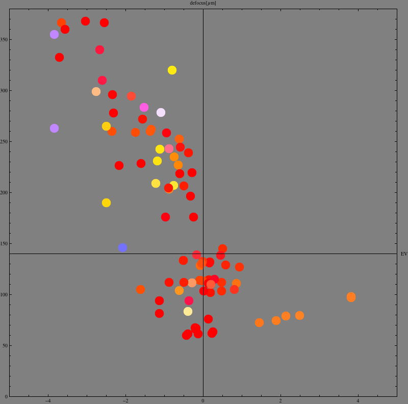
Fig. 14: AF performance with white balance set to Daylight (left) and Manual/Auto (right).
The Manual balance was done for tungsten. There seems to be an advantage for the Manual/Auto results. But it isn't significant: all results lie within the cloud of results obtained for Daylight. There was no significant difference between Auto and Manual either.
Results are for the FA 31 Ltd. at f/1.8 and 1 m distance.
While below, I always check for a white balance effect before aggregating results, I already present the corresponding result now:
Finding 14: Firmware 1.03 doesn't introduce a white balance setting dependency.
5.2. Constant lens, aperture and distance
The following replicates the corresponding test done for release 1.02.
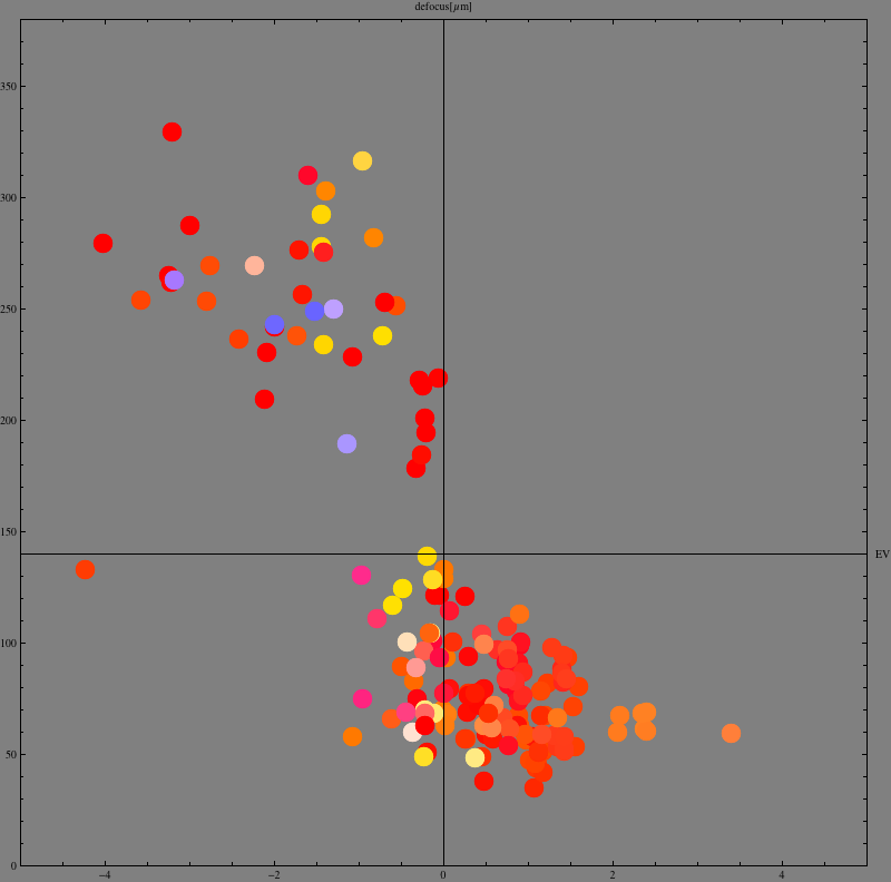
Fig. 15: AF accuracy with firmware 1.02 (left) vs. 1.03 (right).
Results are for the FA 31 Ltd. at f/1.8 and 1 m distance.
The caption is the same as for Fig. 4 on p. 10. A few new measurements have been added to 1.02 results and the scale has been adjusted to match the 1.03 results.
The sad truth is that firmware 1.03 didn't bring any improvement at all to low light focus accuracy in the testing situation as defined here.
Finding 15: Firmware 1.03 has no impact in a situation where AF assist light is off, the background is white, the contrast is high, and the lens is as fast as f/1.8.
Therefore, I carried out a number of additional tests to figure out what Pentax actually changed.
5.3. Dependency on the lens
As we already know, the biggest dependency is one on the lens, probably on its maximum (nominal) aperture.
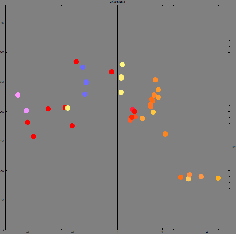
Fig. 16: AF accuracy with firmware 1.02 (left) vs. 1.03 (right).
Results are for the DA* 60-250 at f/4.0. The 1.03 results are at 3 m distance and 60 mm focal length. The 1.02 results are as described in the previous chapter.
The three orange (tungsten) 1.03 dots at ~EV 2 above the 140 µm line are from the Daylight white balance. But again, an effect of the white balance setting isn't statistically significant.
I did not find a significant effect of firmware release 1.03 with the DA* 60-250 lens. If at all, there is an intermediate region around EV 0-2 where the focus shift does still happen. But not always and not as pronounced. Note however, that not all measurements are at equal focal length and distance.
Another effect is that true daylight seems to focus more accurately at very low light levels.
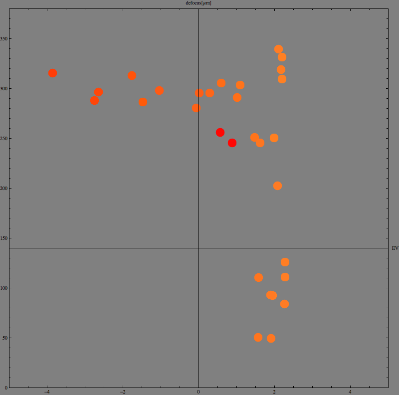
Fig. 17: AF accuracy with firmware 1.03.
Results are for the DA 18-55II at f/5.6 and are at 3 m distance and 55 mm focal length. The white balance setting has no effect and Auto and Daylight are merged above.
The f/5.6 moves the focus shift up although not by as much as a full EV step. At the same time, overall focus accuracy decreases (which most won't see because of the smaller aperture stop in use).
I don't have 1.02 data for the 15-55 to compare with. But with now three lenses studies, I don't think that the 1.03 release brought improvement for just a few "gifted" lenses..
5.4. The Red target
Another possible change is the treatment of color variation throughout the subject. The Red target AF performance in tungsten light is a good test as it may fool the colorimetric measurement.
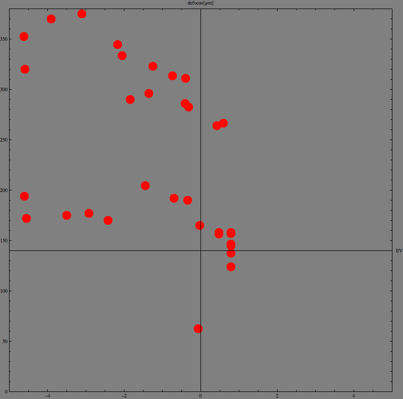
Fig. 18: AF accuracy for a red focus feature in (not red) tungsten light.
The first is for firmware 1.02 and the FA 31 Ltd. at f/1.8 and 1 m distance (same as in Fig. 13 to the left). The second is the same for firmware 1.03. The third is for the DA* 60-250 at f/4.0, 3 m distance and 60 mm focal length and firmware 1.03 again.
The results aren't as conclusive as I wished them to be. As it seems, there may be a chance that the firmware 1.03 is more easily fooled by an overall color which differs from the AF spot color.
This may be a good thing actually as it may help determine the correct color in cases where AF spot color and overall color do match and where the AF spot or background are dark or the lens is slow.
Interestingly, the K-5 with the kit lens (at 55 mm) didn't meter lower than 8 s which is 2.3 EV (ISO 80 and f/5.6). It continued to lock AF focus below. But this allows to determine the light level all 77 metering zones combined can still handle. This corresponds to -1 EV at f/1.8. I am pretty sure that the focus shift simply happens when the colorimetric information stops to flow.
5.5. Overall results
These are my results with respect to the low light focus update embedded into firmware 1.03:
-
1.In many situations (all I tested), the focus accuracy remains unaltered.
-
2.There still is the EV transition area (which shifts to higher EV with higher lens max. aperture numbers) below which the focus lock jumps to front focus by more than 200 µm; i.e. Pentax did not yet address the root cause of the problem.
-
-
◦.The focus still locks where it really shouldn't,
the AF module still doesn't "talk" to the colorimetric sensor.
-
-
3.The front focus transition with slower lenses looks a tad less binary now where there may be an intermediate region (spanning about 2 EV) where results are sometimes (although not always) a bit better than with 1.02.
-
4.Firmware 1.03 may use color information from areas outside the AF spot. More so than 1.02. This may improve results a bit in many cases and worsen things in some.
-
5.1.03 may or may not improve results with a dark background (not tested by me).
-
6.1.03 may or may not improve results due to improved AF assist light behavior (not tested by me).
-
7.1.03 may or may not improve overall focus accuracy in better light (not tested by me).
6. Background on the K-5 phase AF module
I'll spend a few more words asking for possible causes of the issue. Therefore, let's first have a look at the K-5 AF module.
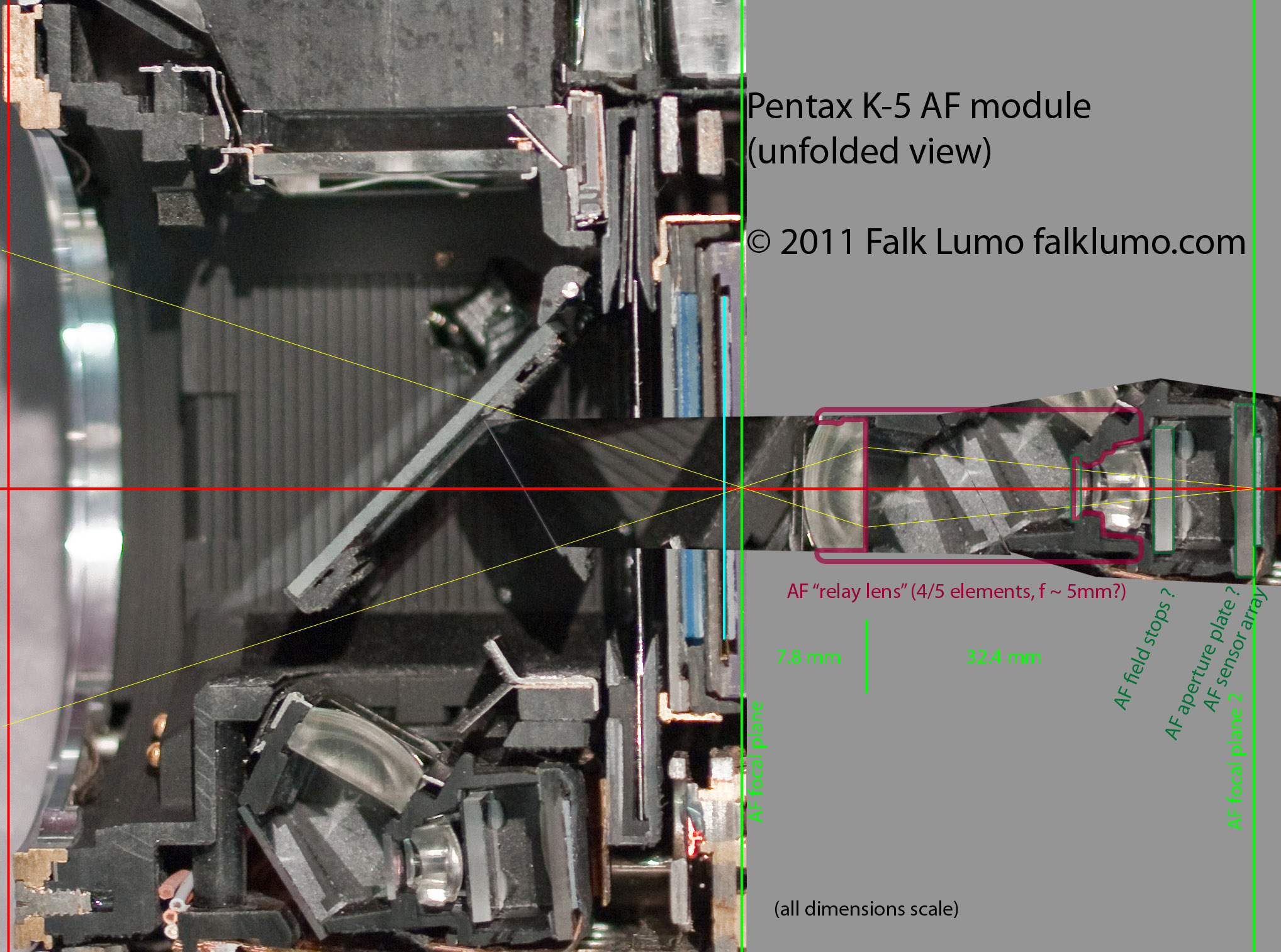
Fig. 19: The Pentax K-5 phase autofocus module. From own research and photographs.
(Cf. text for further explanations.)
The phase AF module sits in the bottom of the mirror box and is composed of mirrors, lenses, boxes and a sensor. In Fig. 19, I've "unfolded" its optical path which is bent by two mirrors: the auxiliary AF mirror attached to the main mirror and a mirror in the AF module itself.
After unfolding, the optical path for the AF sensor is about 40 mm longer than for the main sensor!
This takes already into account that the main sensor's optical path is 2 mm longer than it appears due to the refractive index of the antialias filters.
The AF module "looks" at the out-of-focus image formed about 6 mm behind the main focal plane ("AF focal plane") and refocusses this image onto an AF sensor sitting at the secondary focal plane (AF focal plane 2) 40 mm behind the main sensor.
The lens doing the refocussing (the "AF relay lens") looks a bit like a reversed tele lens actually magnifying the image. It seems to have about 5 lens elements. So, it is probably complex enough to be of an achromatic type and indeed, two lens elements look like achromatic pairs.
Behind the relay lens come two rectangular boxes ("AF field stops?" and "AF aperture plate?") and the AF sensor sitting right at the bottom of the second box.
The basic design principle of a phase AF module is described in the paper "Principle of the Split Image Focusing Aid and the Phase Comparison Autofocus Detector in Single Lens Reflex Cameras" by Douglas A. Kerr, P.E. 2005 [dougkerr.net/pumpkin/index.htm or PDF].
In Fig. 19 and in the text below, I try to use a convention compatible with Fig. 13 on p. 13 of Doug's paper. Fig. 13 and 14 of said paper probably provide the best explanation and can be read without an interest in the working of split prism focussing screens.
However, Pentax seems to use a more complex relay lens and AF field stops which aren't in the virtual main focal plane (this space is empty) but close (in front of) the secondary focal plane (the box right after the relay lens). The box right in front of the AF sensor (which is the last element easily identified by its electrical wires) probably contains micro-lenses focussing the partial rays onto different (linear) fractions of the AF sensor. The position this close in front of the sensor combined with field stops a couple mm away probably minimizes a chromatic dispersion effect compared to Doug's simpler design. Nevertheless, the relay lens seems to be achromatic but doesn't seem to be apochromatic and suffers from longitudinal chromatic aberration.
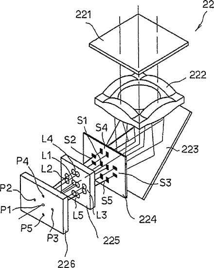
Fig. 20: Hypothetical Pentax AF module as described by Hoya patent US 7,646,979 B2.
Pentax filed patent US 7,646,979 B2 which describes an AF module similar to the SAFOX+ module. Be aware though that it differs from the real K-5 module in a number of ways. Most notably, it describes 5 linear AF sensors rather than 9 cross-type plus 2 linear AF sensors and an extremely simple AF relay lens (cf. Fig. 20).
Nevertheless, we may identify the box labelled "AF aperture plate?" in Fig. 19 with "225" (micro-lenses) in Fig. 20, and the box "AF field stops?" with "224" (field apertures indeed). The plate within the relay lens close to the rear element (I marked the spot by a green border in Fig. 19) probably is the infrared (IR) cut filter ("221" in Fig. 20) and is positioned differently.
Fig. 15 and 16 of Doug's paper illustrate the effect of imperfect focus of the main lens. The contrast of signals to be cross-correlated is reduced affecting the accuracy of the determined phase.
I could not identify the so-called "+" color sensor in the K-5's SAFOX IX+ AF module. Four One possibility come to mind:
-
1.The color is measured by the AF sensor itself.
-
2.The little spot within the relay lens does it (although signs of its electrical contact in Fig. 19 are difficult to identify).
-
3.The color is measured outside the module (e.g., as part of the 77 zone light meter).
-
4."+" stands for an achromatic relay lens, not a sensor.
The patent helped to clarify this and option 3 could be confirmed (cf. below). The withdrawn options from v1.0 of the paper have been stroked thru.
Given all this background, it is worthwhile to ask for the nature of color dependency of AF measurement. The simpler module as described by Doug's paper might see rays of different colors at different angles (due to prism dispersion), making the distance between virtual apertures (and the phase distance conversion factor) color dependent (however, my thinking may be wrong here).
I am not sure though the K-5 module would have this problem. So, it was helpful to find Fig. 21:
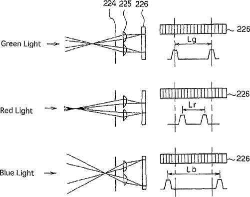
Fig. 21: AF focus errors due to longitudinal CA of the AF relay lens (from the Hoya patent).
If you look careful, you'll find that the depicted CA is that of a single element lens. But even an achromatic lens (which I suppose the K-5 to have) would have Lr = Lb ≠ Lg.
Therefore, I assume the K-5 uses an AF point-color correction look-up table to correct for CA of the AF relay lens which isn't apochromatic.
This color correction look-up table requires a color measurement (the K-5 AF module has no color filters – it could but doesn't).
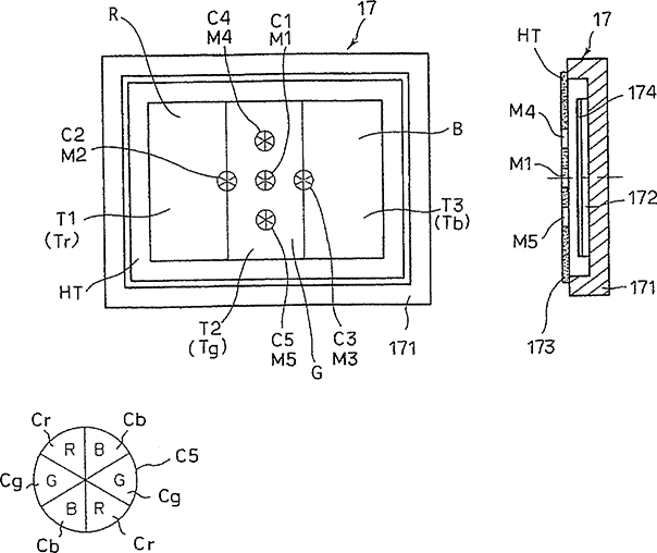
Fig. 22: Hypothetical Pentax colorimetric sensor as described by Hoya patent US 7,646,979 B2.
The sensor sits above the eye piece behind the prism and looks onto the focussing ground plate image. In the patent, it sits right above the photometric (K-5: 77 zone) sensor behind a dual lens projecting an image for each of the two sensors (colorimetric and photometric). The K-5 doesn't have two sensors.
The patent describes a colorimetric sensor which measures two things at the same time:
-
1.The color at the AF point (called the colorimetric sensor) (C1/M1 – C5/M5).
-
2.The global color (called the light temperature sensor) (Tr, Tg, Tb).
The sensor is described to be separate from the photometric (K-5: 77 zone) sensor. However, the K-5 has a single sensor only and therefore, the colorimetric "SAFOX+" sensor must be merged with the photometric sensor (cf. Fig. 23).
An interesting observation is that SAFOX+ AF and 77 zone metering are two features which always come together (Pentax K-7, 645D and K-5, and only these). Which makes me believe that the 77 zone photometric sensor in fact is a 77 zone photometric & 11 point colorimetric "+" sensor. I checked how the 77 zones of the photometric sensor and the 11 zones of the SAFOX+ AF system do actually match (cf. Fig. 24).

Fig. 23: Pentax K-5 combined colorimetric & photometric sensor (from the K-5 cut model photograph). It sits right above the eye piece (the penta prism is to the left).
The plate between the combined sensor and the lens must be the IR cut filter which replicates the IR cut filter of the AF module (a Canon patent quotes an IR cut filter behind the prism be required).
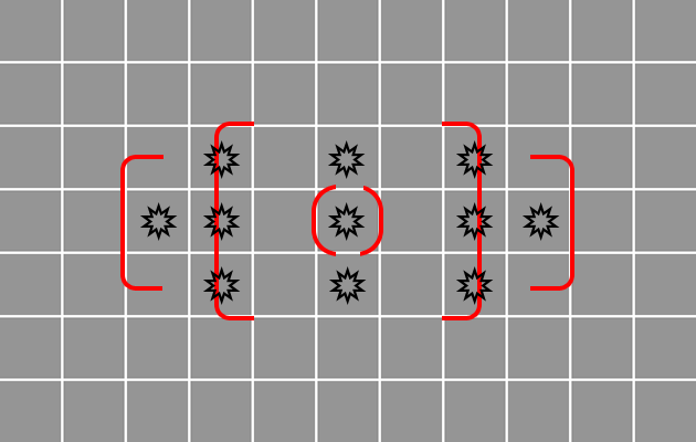
Fig. 24: Overlay of the Pentax K-5 focus guides (red) and the 7×11 metering zones, with the hypothetical positions (star symbols) of the 11 colorimetric sensors. I verified the guide positions by looking at this diagram through the K-5 100% viewfinder :)
Note that the AF sensors are 1 square high (the two edge sensors are twice as high) and 4/3 squares wide (the two edge sensors have zero width). The cross sensors have "+", "T" and "L" shape, resp.
I cannot but take notice that the focussing guides and the 7×11 grid are a perfect snap.
The match actually is good enough to support my combined sensor hypothesis. Maybe, Pentax included an RGB filter with every of the 77 cells to circumvent a Canon patent using a similar layout to Fig. 24 (which negatively impacts exposure metering as laid out in the Pentax patent).
Moreover, the original Pentax patent with a separate light temperature sensor is redundant for two reasons: The light temperature can be guessed well enough from integrating over AF point colors and eventually gets replaced by the white balance as computed from the taken photograph.
Therefore, I assume that the combined 77 zone exposure sensor also determines color at the 11 AF points and integrates them for a light temperature reading, i.e., it delivers 77 gray values, 11 RGB values and one global (and low light) RGB light value (a total of 113 scalars).
7. Some ideas for possible causes for low light front focus
Equipped with test results and the anatomy of the AF sensor, we can speculate. What may cause the K-5 to lock front focus?
Frankly, I don't know. But I do have an idea (a theory).
I don't think its an effect directly related to light color. Rather, I think that red light equals less light and emphasizes a problem which in itself, isn't much light color related. Moreover, it is a surprising finding that the amount of defocus (≈ +250 µm) is less variable than the luminosity trigger when it happens which seems to be lens dependent.
This implies that I don't think infrared plays any rôle here. This is confirmed by many who tried to cure the problem by installing an IR filter (with no or little luck). And the AF module seems to have its own IR cutoff filter anyway.
Most importantly, the effect is non-linear. The AF jumps from normal state to front focus state with little variation of its input parameters. This is a phase transition and can only be caused by three mechanisms:
-
●.interaction of many system components.
-
●.quantization (software or digital hardware).
-
●.a nonlinear component like a trigger etc.
We may assume that Pentax would have fixed a trivial cause already.
My theory is that the color measuring component (which receives light from outside the AF optical path) returns an "overflow" result for low light which then causes the firmware to falsely correct the focus operation. It would help if Pentax would write an AF correction value (if it exists) into EXIF data. By "overflow", I mean any out-of-range event or any event which writes 0xFF into a byte.
BTW, I see AF integration times (as found in the EXIF data) between <1 ms (sunshine) and 250 ms (in low light). So, there is a maximum integration time. Also, EXIF contains a "defocus" value which is zero or small in sunshine, but up to 15 in low light. It can be larger with contrast AF (the phase AF module still works and writes its values...) and I've seen one value as large as 255. It also contains "WB shift" values but they are all zero in my case.
Integration times of 250 ms (¼ s) are immune to flicker from artificial light sources too and we can exclude another possible explanation. A max. AF integration time of 250 ms does not by itself trigger the focus shift (cf. Fig. 25).
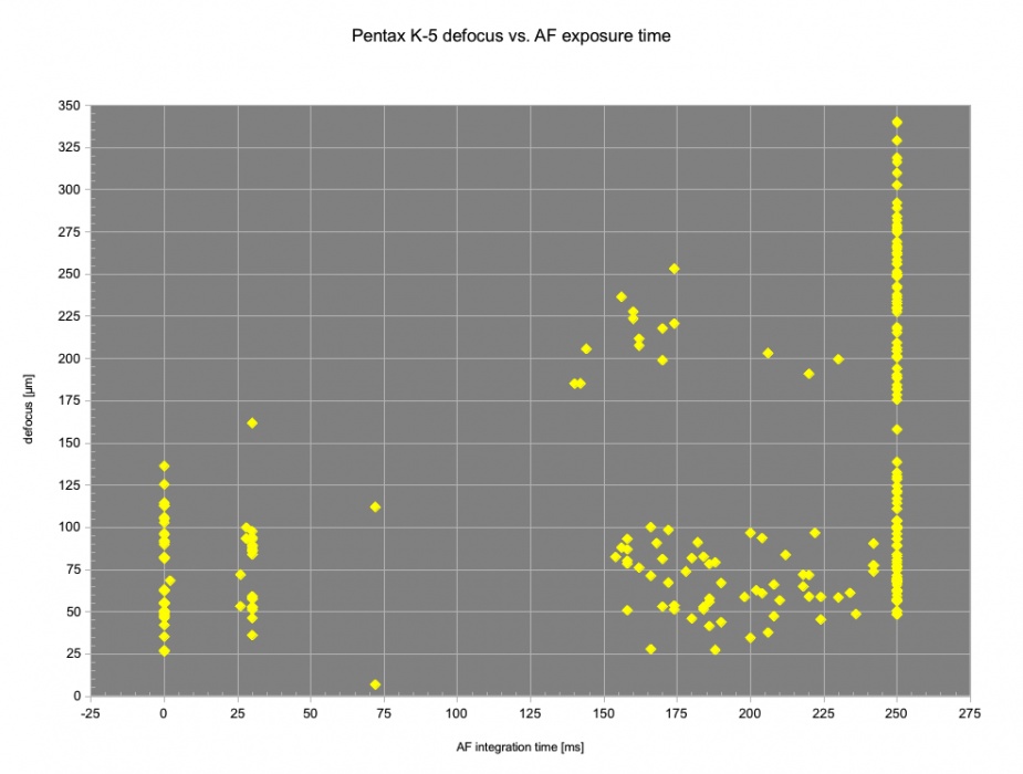
Fig. 25: Defocus as a function of EXIF data AF integration time.
Maybe, the defocus of ≈ 250 µm actually is some 255 internally (if there is a µm-based variable somewhere which I believe to have seen once in some lens calibration debug menu). And 255 is a good candidate for an "overflow" value (-1 or 0xFF). Of course, it would require a firmware variable to use a µm unit (or close to). Not likely but possible. Who knows.
I'll call it the +0xFF µm hypothesis.
Of course, I can be totally wrong again ;)
Another possible explanation is motivated by the following experiment: If one illuminates the eyepiece with a white LED flashlight while the scene is tungsten-lit, the amount of defocus seems to be about the same. While it is zero with a tungsten flashlight into the eyepiece. Therefore, the following scenario probably is more likely actually:
-
1.At good light, the AF point color is measured and used to correct for AF module CA.
-
2.At moderate light, the AF point brightness becomes too low for a good reading and the integrated value of all 11 points (the light temperature) is used instead. This works well for a white or gray target (3.5 EV more latitude) but should lead to early "fails" with colored edges to be in focus.
-
3.At low light, even the combined output is too low for a good reading and the AF module (unfortunately) falls back to a daylight default (i.e. no) correction value. The difference between daylight (green) and tungsten (red) then is a hefty 250 µm which may be due to the higher AF module partial ray aperture.
So, the embedded colorimetric sensor isn't light-sensitive enough, esp. with a slow lens and/or a dark background. Exactly what we measured.
I'll call it the dark is daylight hypothesis.
In this case, a fix isn't as simple as fixing a firmware bug. It requires a new menu entry to manually enter (or measure) the focus target light color (where in the studio, modeling light and strobes differ in light temperature to further complicate things). The easiest way may be an option to tell the camera that the focus target light color shall be taken from the previous shot in memory (which must be w/o strobe in the studio).
The least thing the camera could do simply is to veto a focus lock if the colorimetric reading is too low. No focus is better than false focus! The imminent firmware version 1.03 may be interesting ;)
8. Conclusion
The K-5 as it presently ships has a flaw in its phase detect autofocus module or software which causes it to front focus in low enough light. This applies to both v1.02 and 1.03 firmware releases.
If it does, it seems to consistently focus ≈ 250 µm in-front-of the sensor plane (although with a scatter of results within a ± 75 µm range). It is my opinion that a hardware limitation is the root cause and an appropriate treatment to workaround this limitation in the firmware is still missing.
For any dSLR camera, the scatter of normal focus operations is significant too (around ± 30 µm for the K-5) and the larger scatter of results in the low light regime probably is just due to that: less light.
Faster lenses seem to keep working in lower light but of course, are prone to more blur when the front focus does eventually happen. Slower lenses can already start to front focus at light levels metering as 4 EV or 6 EV even. A fast lens may work down to 0 EV in white light. Moreover, dark background intensify the problem considerably as it is the overall level of available light (as visible on the focussing ground plate) which determines the effect.
In a low key studio situation with a slow lens like the DA 15/4 Ltd., it may even happen at light levels one would never guess.
Light sources other than daylight emphasize this problem as they simply appear darker to the AF module. Moreover, it seems to be moderately color blind for red which seems to contribute less than the usual 30 %.
It is reported that all K-5 exhibit the same behavior (but this paper studied a single unit only) and Pentax released firmware version 1.03 to reduce the problem. The effect is real and negatively impacts the daily work of many photographers. The reactions to the v1.03 update in the internet have been mixed. Some report a significant improvement while others report no change. This report suggests that the improvement is limited to some situations only.
Therefore, it is quite possible to run into a low light tungsten situation without the problem. This paper clarifies conditions to hit or avoid the issue. White light (halogen is not white enough though) and a wide lens stopped down and a bright background help to work around the problem. AF assist light didn't help with firmware release 1.02 though. But an LED flash light does. ;)
The pressure is on Pentax to continue addressing the issue and the author hopes that this paper may contribute to their efforts. Buyers of the K-5 must be able to be confident that the issue is fixed sooner than later.
The issue now is well documented and implies that the K-5 AF module doesn't work as advertized. The firmware update 1.03 was a step in the right direction. But much of what can be done to work around the problem in the firmware still hasn't been done yet.
8.1. Acknowledgements
I very much thank "Class A" for proofreading an early version of this paper, "dlacouture" for doing crucial experiments and "Ray Pulley" for contributing relevant patent information. All from pentaxforums.com.
❖
View or post comments: click here